Control block diagram of virtual synchronous generator including active Vehicle a/c system diagram How does a hydraulic accumulator work
Hydraulic: Examples.Accumulators.AccumulatorAndCylinderCircuit - System
A: conventional accumulator Understanding the function of accumulators Autonomous cyber-physical systems: synchronous components: ii
Mechanism structure of the new accumulator.
"accumulator" block.Block diagram of accumulator and its operation principle illustrated 1. block diagram of phase accumulatorSimplified block diagram of the device of advance compensation of.
Block diagram of the region accumulatorAccumulator components Dynamic characteristics of coupling model of valve-controlled cylinderAccumulator hydraulic system nitrogen hydraulics use diagrams.

Accumulator hydraulic schematic control hydraulics accumulators charging energy electrical systems adiabatic isothermal respect differentiate terms between
Block diagram of accumulator structural model: (1) accumulator emf; (2Hydraulic: examples.accumulators.accumulatorandcylindercircuit Proposed scheme of accumulator-regulators(get answer).
Block diagram of active and reactive power control systemBlock diagram of the digital accumulator. Accumulators accumulator hydraulic fluidpowerjournalThe operating diagram of the proposed fully pipelined accumulators.

Controlled accumulator model.
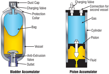
Accumulator hydraulic does workAccumulator components Block diagram of active and reactive power control systemWhat is bladder accumulator? construction, diagram, working.
20-sim webhelp > library > iconic diagrams > hydraulics > volumesUsing a power accumulator for real-time power measurements. part 1 Component transcribedUnderstanding the function of accumulators.

Draw the block diagram of accumulator based cpu and explain the
Accumulators accumulator understanding fluid fluidpowerjournalAccumulator device component 3.2 accumulators – hydraulics and electrical control of hydraulic systems10: energy accumulator block diagram.
3. block diagram of the accumulators (acc) shown in 2.Solved consider the synchronous reactive component shown in Wolfram hydraulic accumulator accumulatorsPower accumulator block diagram measurements using real part time figure.


a: Conventional Accumulator | Download Scientific Diagram
20-sim webhelp > Library > Iconic Diagrams > Hydraulics > Volumes

Hydraulic: Examples.Accumulators.AccumulatorAndCylinderCircuit - System

Solved Consider the synchronous reactive component shown in | Chegg.com

Using a power accumulator for real-time power measurements. Part 1

Simplified block diagram of the device of Advance compensation of

1. Block diagram of phase Accumulator | Download Scientific Diagram

Autonomous Cyber-Physical Systems: Synchronous Components: II - ppt
